Description
5-36V Relay Module Switch Trigger Time Delay Circuit Timer Cycle LED Display AU
Descriptions:
– Band New & High Quality
– Versatile multifunctional timer and delay unit
– Compact Digital LED Time Delay Module featuring a dual-MOSFET’s for lower resistance, more current and more power operating at room temperature. Can be used for controlling lights, DC motors, pumps, solenoid valves and many other applications.
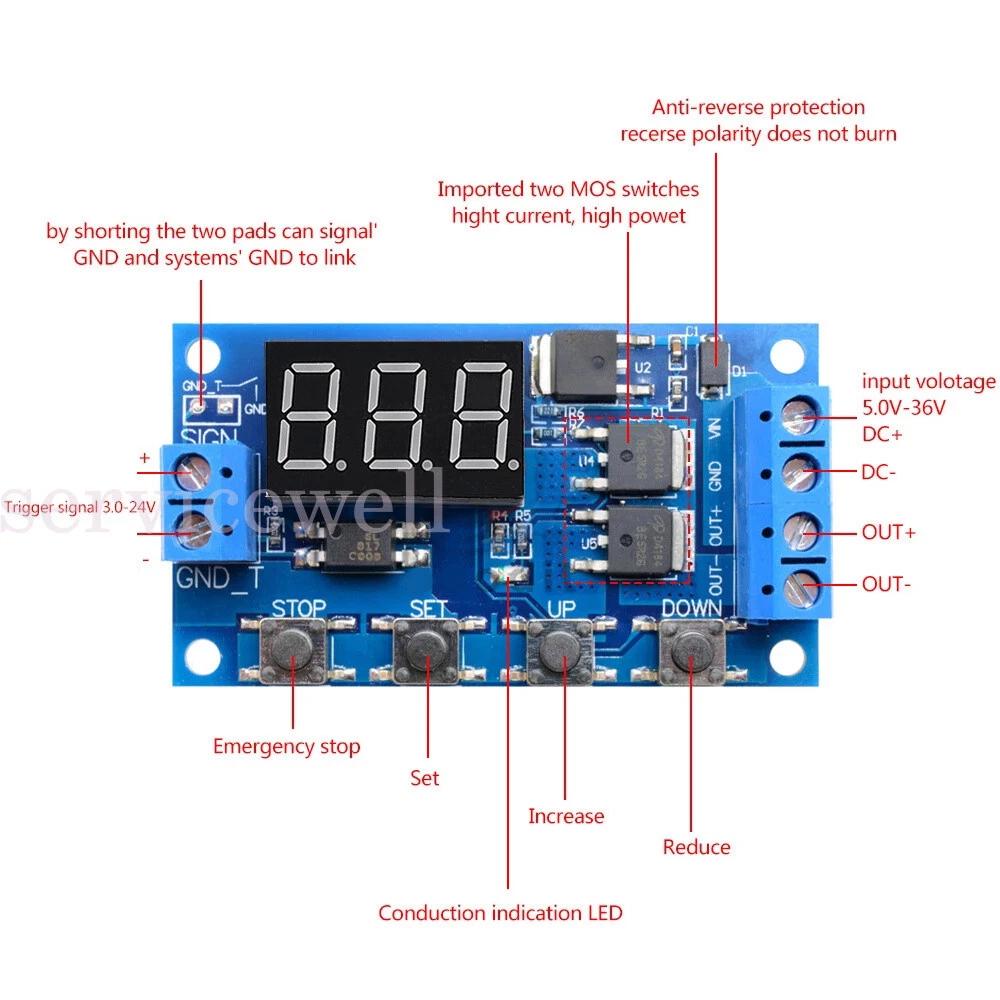
– Input Voltage: DC 5V~36V (reverse polarity protection)
– Output Capacity: DC 5V~36V (output voltage will be equal to the input voltage)
– Continuous Current: 15A, 400W
– Max Current: 30A (enhanced heat dissipation recommended with heavy loads)
– Trigger Signal Source: DC 3.0V~24V
– Quiescent Current: 15mA
– Working Temperature: -40 ~85
– Clocking (Time Delay) Range: 0.1 seconds to 999 minutes
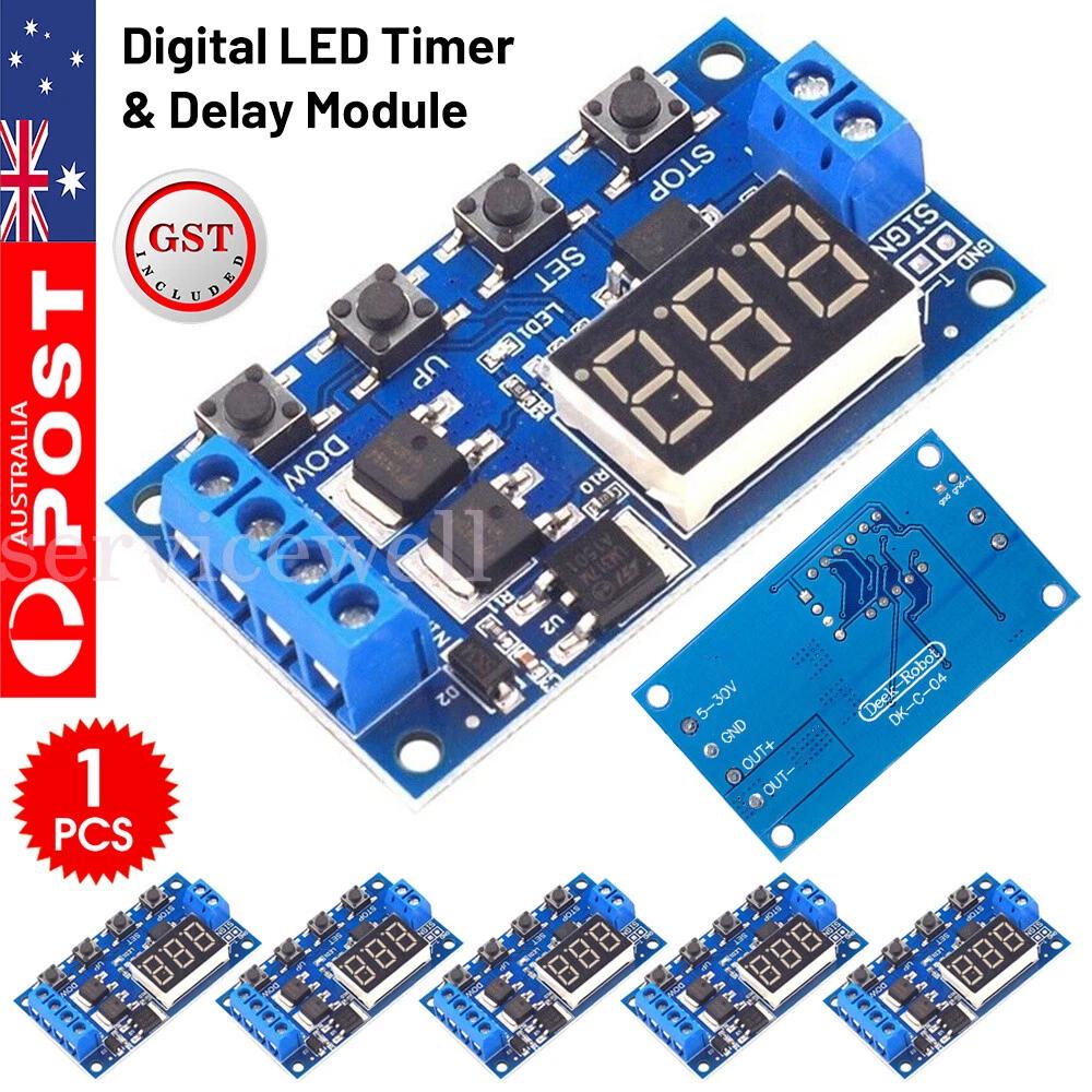
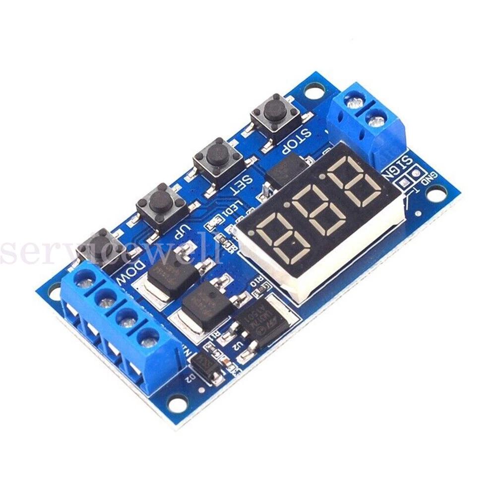
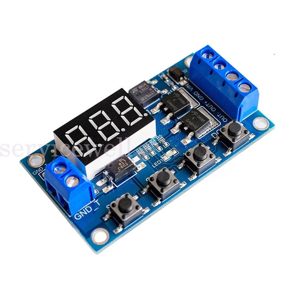
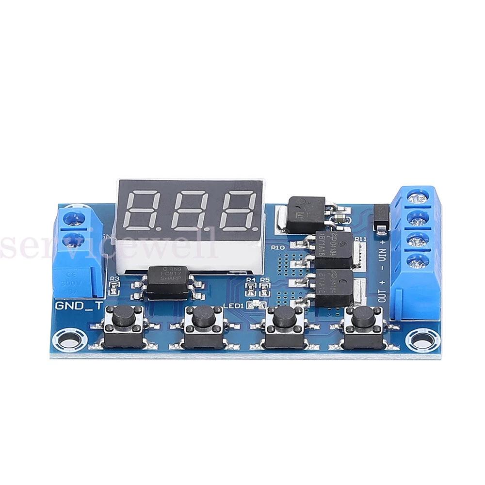
– Size: 60x34x12mm approx.
Parameters Explained:
Different OP, CL and LOP parameters can be set, which will run in various configurations depending on the program you set. OP, CL and LOP are defined as follows:
OP = Time load is turned on. (operating time) – 0.1 sec to 999 min
CL = Time load is turned off (cut load time) – 0.1 sec to 999 min
LOP = The number of program cycles (loop times) – 1 to 999 cycles, “—” represents an infinite loop
Selecting a Program:
Connect input power to the module (display will light up)
Hold Set button for 3 seconds and release and display will flash for a second and then display P1.1
Use the Up or Down button to scroll through programs P1.1 / P1.2 / P1.3 / P1.4 / P2.1 / P2.2 / P3.1 / P3.2 / P-4
Once you have selected your desired mode press Set to accept.
Program Definitions:
P1.1 program
When the trigger signal is received: The load will turn On and run for the pre-set (OP) time and then disconnect.
(additional triggers during timer count down will be treated as invalid and load stay on countdown continues.)
(additional trigger after timer countdown will restart P1.1 program.)
OP time setting only in this mode.
P1.2 program
When the trigger signal is received: The load will turn On and run for the pre-set (OP) time and then disconnect.
(additional triggers during timer countdown will restart the OP timer and the load stays on for the extended reset time.)
(additional trigger after timer countdown will restart P1.2 program.)
OP time setting only in this mode.
P1.3 program
When the trigger signal is received: The load will turn On and run for the pre-set (OP) time and then disconnect.
(additional triggers during timer countdown will turn off the load and stop the OP timer.)
(additional trigger after timer countdown will restart P1.3 program.)
OP time setting only in this mode.
P1.4 program
No Trigger Mode In this mode is started by turning on power to the input voltage and does not use the trigger input.
To use, set to mode P1.4 and set the timing range and timer and hold Set for 3 seconds to accept the program (000) and turn off the input power to the module. Each time you turn on the module the OP timer will start.
OP time setting only in this mode.
P2.1 program
When the trigger signal is received: The load will remain Off for the pre-set (CL) time and then turn On for the pre-set (OP) time and then disconnect.
(additional triggers during timer count down will be treated as invalid and CL and OP countdown continues.)
(additional trigger after timer countdown will restart P2.1 program.)
OP time & CL time setting available in this mode.
P2.2 program
When the trigger signal is received: The load will remain Off for the pre-set (CL) time and then turn On for the pre-set (OP) time and then disconnect.
(additional triggers during timer count down will be treated reset P2.2 program and CL load Off countdown will restart.
(additional trigger after timer countdown will restart P2.2 program.)
OP time & CL time setting available in this mode.
P3.1 program
When the trigger signal is received: The load will turn On for the pre-set (OP) time and then turn Off for the pre-set (CL) time and repeat for the number of cycles pre-set for the (LOP) and then disconnect.
(additional trigger after timer countdown will restart P3.1 program.)
OP time & CL time & LOP setting available in this mode.
P3.2 program
No Trigger Mode / Setup and starts up the same as P1.4 mode to activate and runs a program the same as P3.1 mode.
OP time & CL time & LOP setting available in this mode.
P-4 program
Signal Holding Function Load is powered on for a constant trigger signal. If trigger signal is lost, OP timer starts and load powers off on completion of timer. Requiring trigger signal restarts P-4 program
OP time setting only in this mode.
Select Time Range and Set Timer:
Availability to set timing for OP, CL and LOP depends on the program you select (as noted in the program definitions above).
To scroll through the available OP, CL and LOP menu, quick press the Set button.
Once you are on the one you wish to set, quick press the Stop button to move the decimal point
000. = 1 second to 999 seconds (e.g. 012. is 12 seconds)
00.0 = 0.1 seconds to 99.9 seconds (e.g. 14.3 is 14.3 seconds)
0.0.0. = 1 minute to 999 minutes (e.g. 0.2.3. is 23 minutes)
Once you have set the time range, use the UP and Down buttons to set the time.
Repeat this for each OP, CL and LOP as required.
Once all settings are completed hold the Set button for 3 seconds, release and the counter will display 000 and your module is active.
Power Enable Mode:
ON: allows power to the load in “OP” time;
OFF: prohibits power to the load in “OP” time.
Once your module is active you can quick press the “STOP” button to switch between ON and OFF, this can be used to override the program and stop power to the load when a program is running.
Sleep mode:
“C-P” Sleep mode: 5 minutes no operation, the digital display turns off, programs continue to operate normally;
“O-d” normal mode: digital display always on;
Press the “STOP” button for 3 seconds and then release to switch “C-P” and “O-d” state, in which the current state flashes and then return to the main screen.
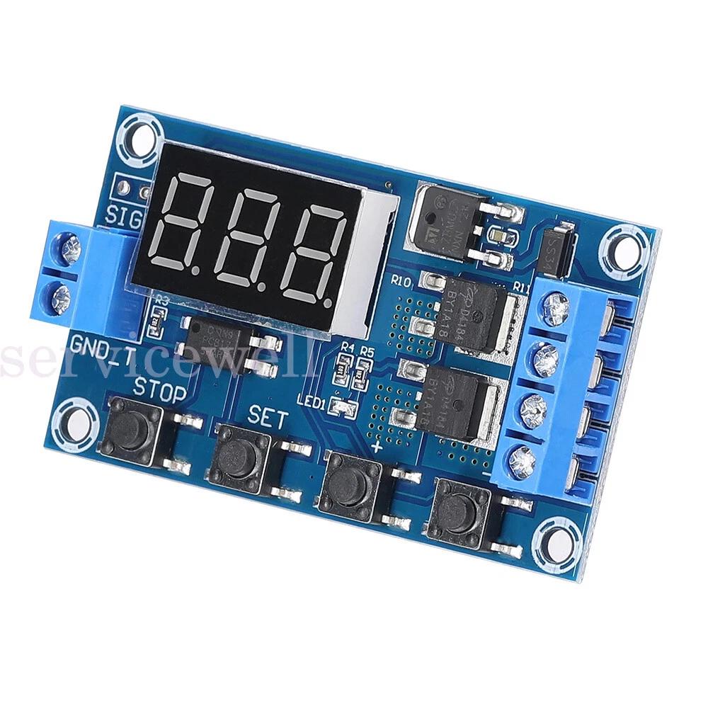
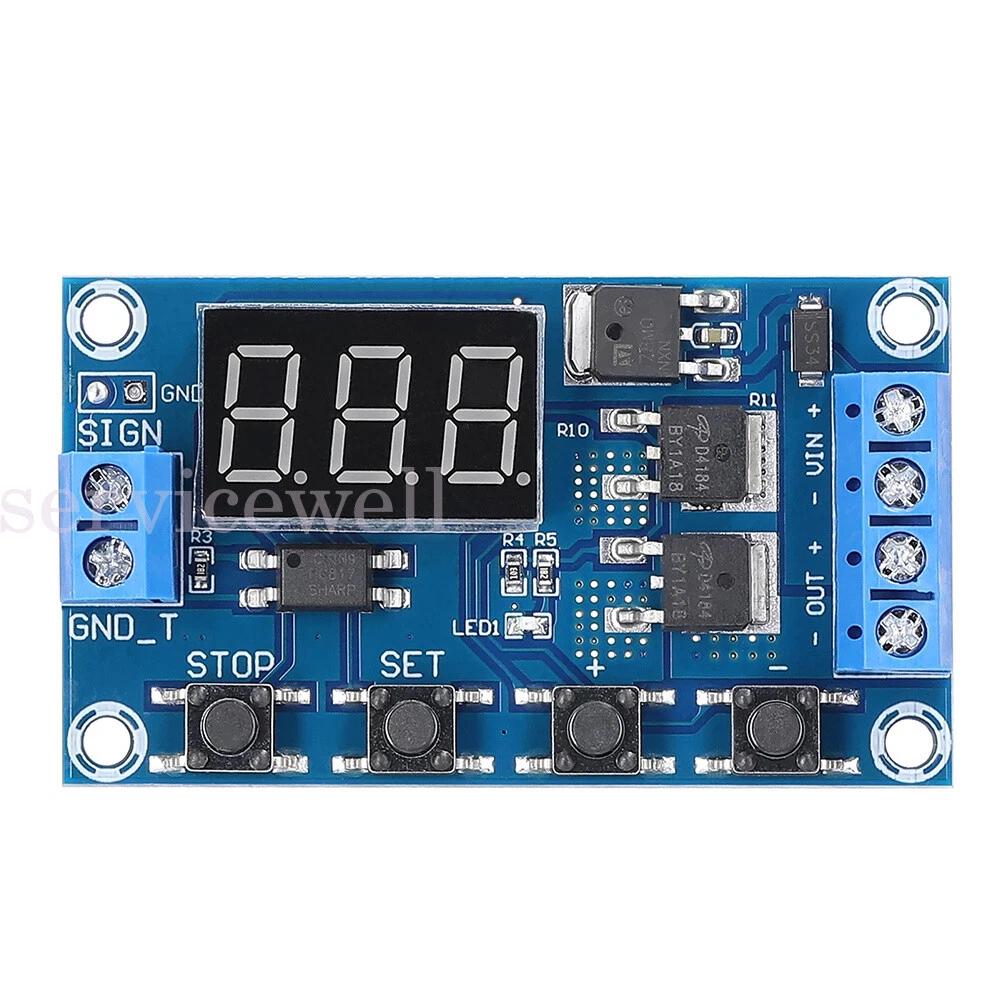
Signal Ground (Trigger) and System Ground (Input/Output) are not a common ground. This improves the system’s anti-jamming capability. The solder pads can be connected if you do wish to run a common ground with this module.
Load circuit is controlled on and off via the DC – / The DC + ‘and’ Load + ‘ are internally connected.
If the module is powered down, your settings will not be lost.”
Additional information
| Brand | Unbranded |
|---|---|
| Qty | 1x, 2x |